Continuity Checking with Sunshine DT17N Multimeter
Learn how to test electrical continuity on smartphone motherboards. Continuity testing helps detect broken tracks, disconnected pads, and PCB line faults during board-level repair.

1. What is Continuity?
Continuity means an unbroken electrical path between two points. Smartphone PCBs contain thousands of tracks that must remain connected for the device to function properly.
- • Detect broken PCB tracks
- • Confirm component connections
- • Identify disconnected pads
- • Essential for board-level repair
2. Sunshine DT17N Overview
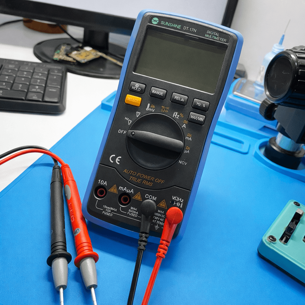
- • Dedicated continuity mode with buzzer
- • Fast response measurement
- • Clear digital display
- • Accurate low-resistance detection
3. How to Set Continuity Mode
Use the 🔔 Continuity Mode. The smartphone must always be powered OFF.
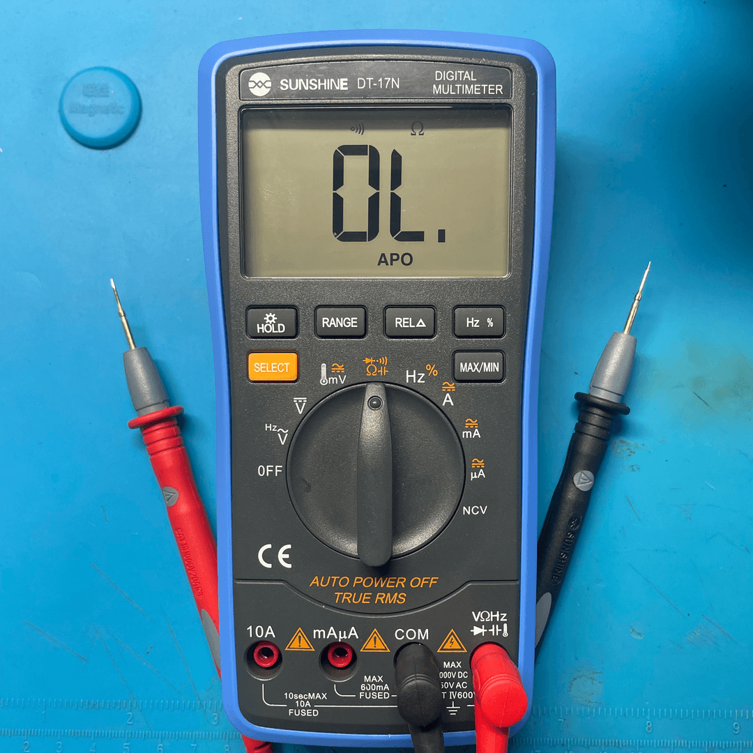
- 1. Turn rotary switch to 🔔 / Diode mode
- 2. Use select button to choose continuity mode
- 3. Black probe → COM
- 4. Red probe → VΩ
- 5. Ensure device is powered OFF
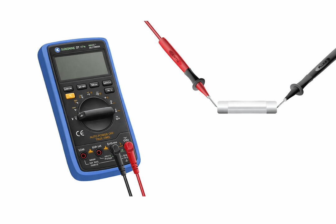
4. Performing Continuity Test

- • Touch probes to two points
- • Listen for buzzer sound
- • Observe display reading
- • Compare with schematic if available
5. Checking Broken Tracks
Continuity testing helps detect broken PCB tracks caused by corrosion, liquid damage, or physical stress.
- 1. Place probe on source point
- 2. Place second probe on destination
- 3. No beep → broken track
- 4. Repair using jumper wire
Result Interpretation
- ✔ BEEP → Track connected
- ✖ No sound → Broken track
- ⚠ Intermittent beep → Weak solder joint
6. Common Continuity Checks
| Area | Test Points | Purpose |
|---|---|---|
| Charging Port | VBUS → IC | Detect charging line break |
| Display Connector | Pin → CPU | Screen signal path |
| Battery Line | BAT+ → PMIC | Power delivery |
Safety Tips
- • Never test continuity on powered devices
- • Use sharp probes for micro pads
- • Avoid slipping probes
- • Disconnect battery if unsure